Building the ISE-NIN DIY an 8 voice polyphonic, MPE enabled Jupiter 8 inspired synthesizer
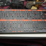
The ISE-NIN mounted in a 19″ Rack
DIY ISE-NIN Specs:
- Inspired by Roland’s Jupiter 8
- 8 Voice polyphonic analogue synthesizer
- Analog VCOs, lowpass and highpass filter, noise generator, two ADSR envelopes and a VCA
- 2 different presets can be layered
- Poly-aftertouch and MPE enabled
Intro
The Jupiter 8 was one of the greatest polyphonic synthesizers ever made. It was extremely versatile allowing the composer to build powerful strings, hard phat leads, deep base and amazing pads. Released in 1981, it sold for a whopping $5295 USD, which is equivalent to over $17,000 in 2023! In fact a used original, working Roland JP-8 will sell for over $20,000 today. The ISE-NIN DIY version is considerably less, and will cost you about $2300 USD. For $1000 Black corp will ship the bare circuit cards, front panel and case to your home. But that is just the beginning. Depending on your experience in component purchasing, quantity, location, etc, all of the electronic components to complete the build could cost you an additional $850 to $1500.
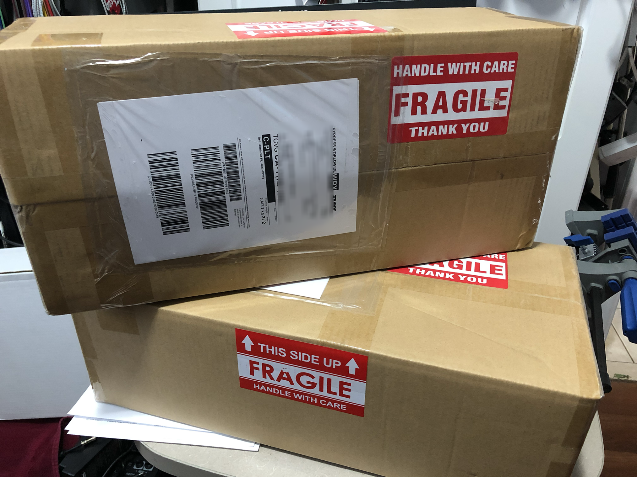
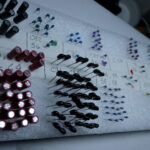
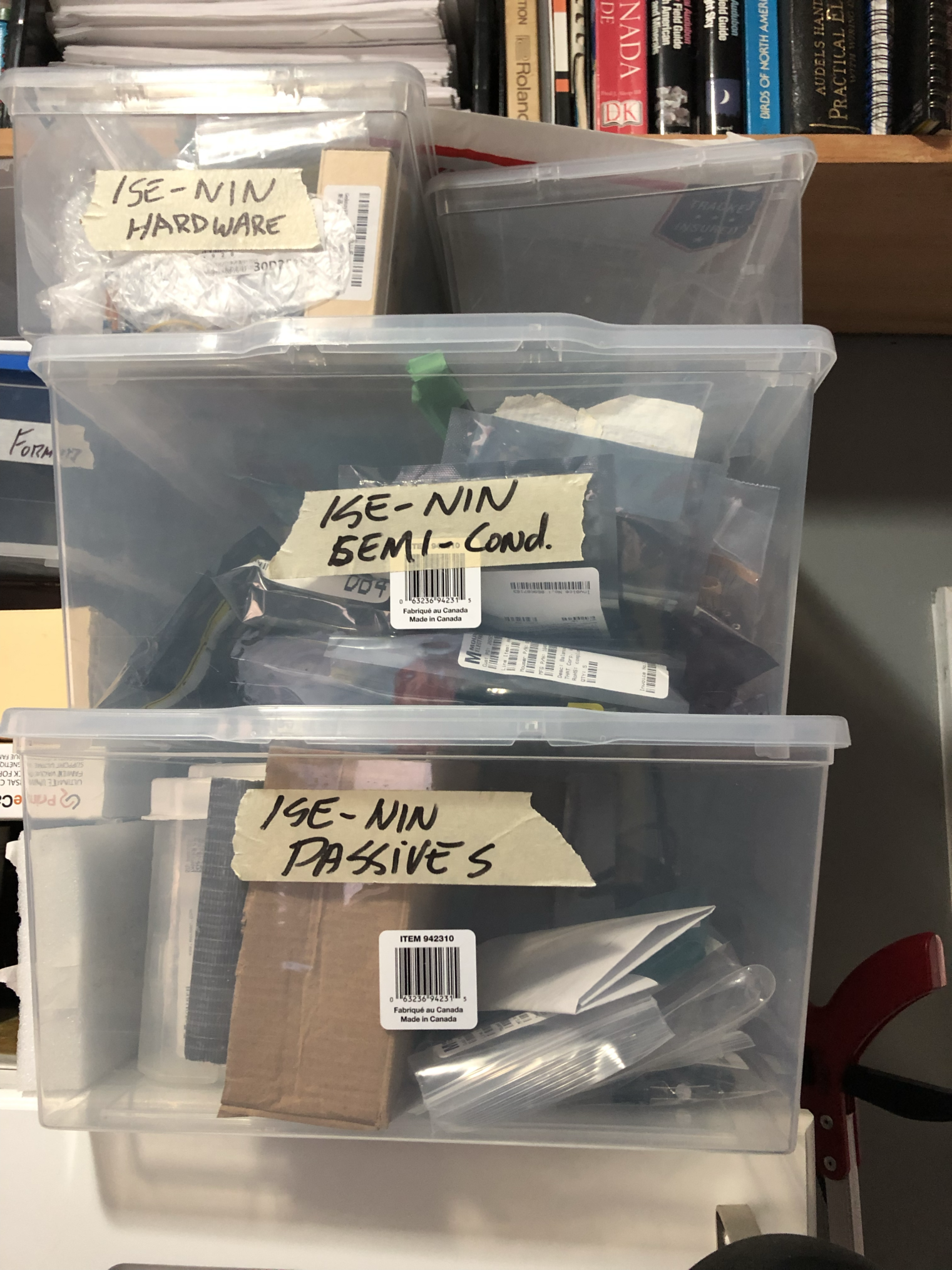
I was able to order 95% of the components from either mouser or digikey Specialty items like the knobs and slider caps can be ordered through the UK based Thonk. Once the components arrive, I generally sort them into 3 separate boxes, passives, semiconductors and hardware. I ordered enough components for 3 synthesizers. I will be building one for another studio and one for another musician. Buying bulk can save also you hundreds of dollars, as the cost for buying resistors individually can be expensive. Buying 200 or 500 bulk resistors of a specific value is only a couple dollars more than buying 5 or 10 individually. If you plan on getting into DIY electronics as a hobby or profession, you should keep a vast supply of 1% resistor values, standard diodes, transistors and capacitors. And do not skimp on quality. Ebay can seem cheaper, but many times you are buying components that did not pass inspection or do not meet specification. Many times I have seen DIY enthusiasts spend hours of debugging only to find a transistor or IC was working, but did not meet the specs from the manufacture, and thus did not actually work in the design.

Weird behaviour from a company with great products.
My biggest issue with Black Corporation is that since the DDRM v1, they no longer provide you with a schematic diagram of their synthesizers. No idea why they do this either, and it could become a show stopper for many. Some folks online say it is to stop (insert name of large company that builds nothing but clones here), but that is pure nonsense. Given a BOM, a bare PCB and modern automated test equipment, a net list can be extracted in less than 30 minutes, and then loaded into a CAD system to show a schematic. Using my reverse engineering skills from my old aerospace days, I was able to make a schematic of the voice, power and I/o boards in less than 6 hours. The motherboard and hardware board are very similar to the architecture of the DDRM, so figuring out how they work is trivial. The big unnamed company, or any company with good equipment can do this far easier. I wish they would reconsider, as 10-20 years down the road, online support for repairing these could become nonexistent. Some compitent builders are going though unnecessary frustration debugging their builds because they have to wait for someone in the online community to guide them through the issue in a bits and bob like fashion. Black corp needs to reconsider this shortsightedness and provide the schematics to those that paid for the kits.
A Jupiter 8 clone?
First off, let’s look back at the Deckard’s Dream (DDRM) DIY synthesizer as it too was labelled a “clone” by some in the synth community. Architecture-wise, the DDRM resembled a Yamaha CS-80. The control functions and approximate layout was very close to the CS-80, but none of the circuitry or components would be found in a CS-80. Yet sound wise, in my honest opinion, Deckard’s dream is a close to a CS-80 as you are going to get. So, it is inspired by a CS-80 but not an identical clone. This can be accomplished because modern electrical design tools enable designers and engineers to determine an electronic circuit, based upon the waveforms you wish the circuit will output. In other words, by using the waveforms from various CS-80 presets as input, you can design multiple electrical circuits that will meet that specification. Electrical engineering is great, there is always several ways to provide a solution.
This brings us to the ISE-NIN as it too, is “inspired”, but this time by the Jupiter 8 (JP-8). It has a similar block architecture, panel layout and functional equivalence. But much of the electrical circuitry is vastly different. The original JP-8 used discrete designs for the VCO, envelopes and VCA and components with very loose tolerances. Thus it had to use a stupid number of trimmers to calibrate it, and then keep it within a desired sound spec. It was expensive to make and purchase and for this reason, Roland released the JP-6 a couple years after. The JP-6 was a 6 voice polyphonic synthesizer that offered some of the JP-8 functionality, but incorporated many integrated circuits for the VCOs, VCA, and envelopes. The ISE-NIN is probably closer in circuit design to a JP-6 than a JP-8, but offers the functionality of a JP-8. Integrated circuits definitely provide a tighter design tolerance-wise, keeping the sonic palette within spec much easier than discrete designs can. Being DIY though, you can build the ISE-NIN as a “loose” sounding synthesizer, or improve the sound and audio quality by using tighter tolerances in components.
The table below provides examples of design differences between synth elements. One commonality is that they all have an identical filter design.
| Synth Section | ISE-NIN. | JP-8. | JP-6 |
|---|---|---|---|
| VCO | SSI2131 | Discrete. | CEM3340. |
| VCF | AS3190 | IR3190 | IR3190 |
| VCA | SSI2164 | Discrete | CEM3360 |
| OPAMP | TL064/72/74 | Various | Various |
| Resistors | 1% metal | 5% carbon | 5% carbon |
| Capacitors | 1-10% ceramic or film | 10-20% Ceramic Disk some poly | 10-20% Ceramic Disk. Some poly |
The Build (Please review the rework required below)
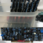
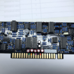
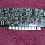
The pcbs are high quality, and well laid out and can handle rework well. In comparison to the Deckard’s Dream, the ISE-NIN has less components but still has enough, that it will take 30 hours of time to complete. The overall construction is very similar too, with the 8 voice cards, the hardware board, motherboard, power card and input/output card. What an experienced builder may find different is the ISE-NIN voice cards are considerably less complex, thus smaller and the I/O board has stereo outputs.

Minimum Tools required.
- Good solder and decent soldering station
- Decent set of wire clippers
- Philips screw drivers, M3 and M4
- Magnification for the SMT components
- A decent multimeter
- An oscilloscope (for filter calibration)
You will absolutely need access to an oscilloscope to calibrate the filters. the synth will work, but it will sound horrible until the voice cards are calibrated properly.
The build has many surface mount (SMT) capacitors on the back side, and 4 integrated circuits on the voice cards also require SMT packages. They however can easily be soldered by hand with a professional or high quality soldering station. Hot air stations or ovens are not required for this build. I suggest builders review Patrick DSLMan’s build guide found here. My own advice is time tested, and can save you heart ache and anguish with trying to debug a project when or if, it does not work when you first power it up.
-
Become organized and eliminate errors most likely to occur before you build.
-
- Develop a consitent workflow or standard operating procedure.
- Test and inspect components when they arrive. Choose a resistor and capacitor from each bag and measure it. Check the transistors and diodes. Mouser and digikey can make mistakes!
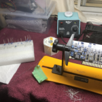
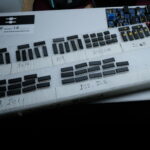
- Assemble build kits for each PCB. I do resistors, then capacitors, then semiconductors. I count out the exact quantity of components for a circuit card and label the on a block of styrofoam. That way, if there is an incorrect value left, or one extra, I know there is a mistake but it is narrowed to that component.
- I also used liquor nail polish (obtained at sale prices), for colour coding capacitors. Given that they are all the same size and same colour, adding the additional colour coding will help you identify specific problem areas or guarantee you did not place an incorrect value.
- Document colour codes, modifications, etc in a build log. I keep a large hardbound note book, and document each synthesizer build.

2. Constantly inspect your work as you progress.
- After each type of component, inspect the solder joints, component legs, etc.
- Measure continuity to ensure voltage rails are not shorted
- Don’t be afraid to use a marker, tape or paint to denote certain aspects of the build right on the PCB.


Test your power card BEFORE you plug it into the motherboard.
The DACs and CPU on the motherboard are very unforgiving should they experience an incorrect voltage. Many kits are destroyed because people prefer a smoke test over a working multimeter.
- Test for shorts across voltage rails before any power is applied.
- You should test the power card and ensure it is working before plugging it into the motherboard.
- Test the power with the motherboard before plugging in any voice cards or attaching the hardware board.

A note on cleaning PCBs.
- Before soldering anything, I wipe the PCBs with 100% pure alcohol.
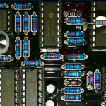
- I only clean my printed circuit boards after the surface mounted components are installed first. I install the SMT capacitors and then SMT ICs only, Then clean the PCBs. This is only done to ensure I can inspect them under a microscope properly.
- For all other components, I use a no-clean solder which has a non-corrosive flux that hardens and provides some protection from moisture.
- All boards get an inspection and are wiped off with a soft nylon brush and then stored in a container when completed. This keeps metal cuttings, solder blobs and foreign objects from causing a possible issue.
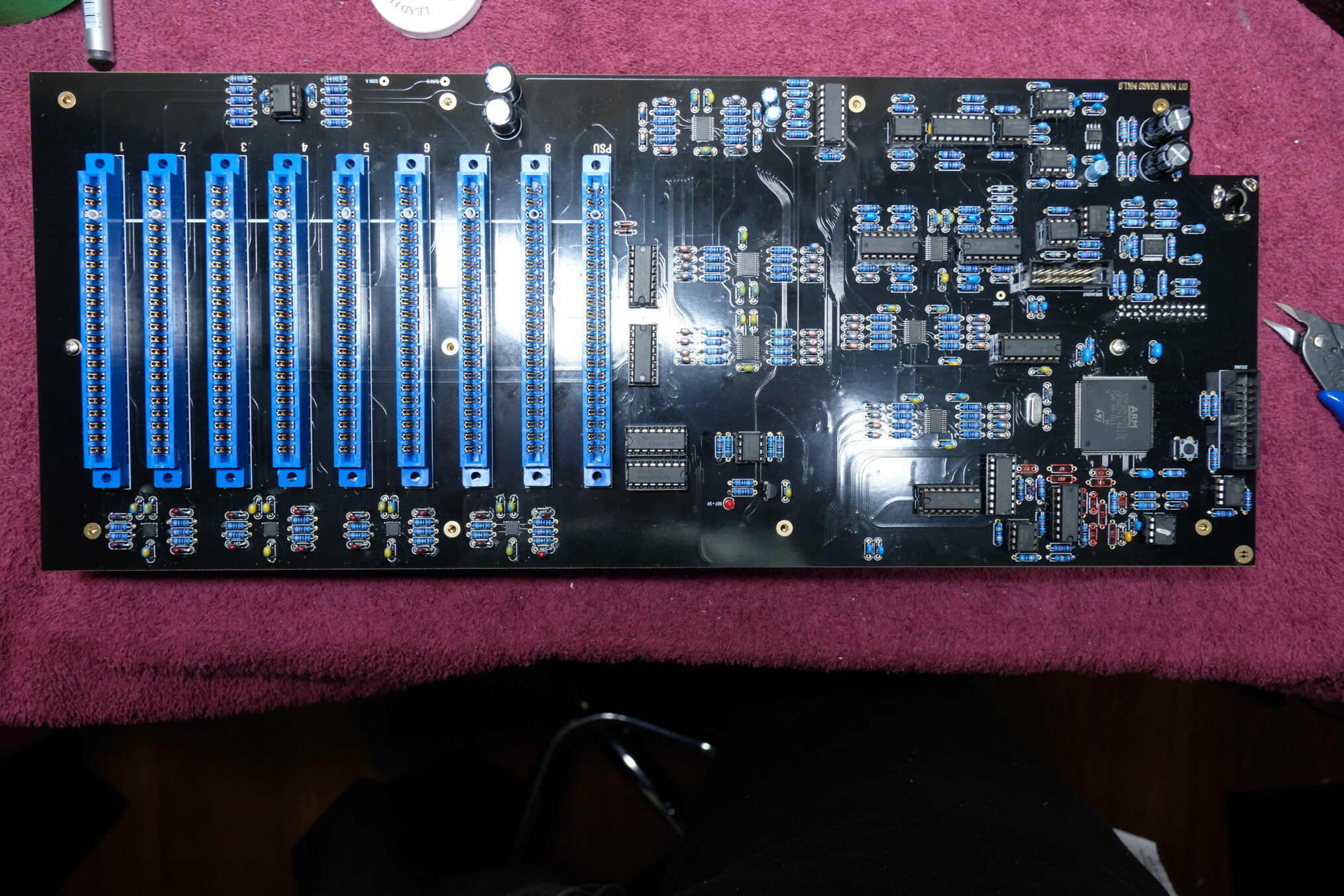
Completed ISE-NIN Motherboard
Assembling the hardware board and front panel.
For ensuring all the switches, sliders and LEDs are all at the correct height for the from panel, my process is as follows:
- Install all non-mechanical components and LEDs.
- Install the standoffs that go between the hardware board and front panel.
- Place the sliders, switches and rotary encoders into their position but do not solder them.
- Place the panel on and ensure the components are mounted correctly and that the panel fits over them.
- Screw the front panel to the spacers, flip the entire assembly over and support the panel so that all of the components are not obstructed or hitting the table, and sitting evenly in their slots and holes.
- Tack solder a couple pins of each component. Check the components (flip the assembly over and ensure they are all even).
- Finish soldering the components. Do not overheat the sliders.
- Remove the front panel, then proceed with placing the LEDs in the same manner.
- Insert the LEDs, place the panel back on.
- Push the LED leads from the back to seat the LED into it’s hole
- Solder one lead of each LED, flip the assembly, check the LEDs from the front
- Solder the rest of the leads and clip them off.
- Then move onto the display in the same process.
Note: Some builders used flat top LEDs instead of the BOM listed round tops. They can look pretty cool.


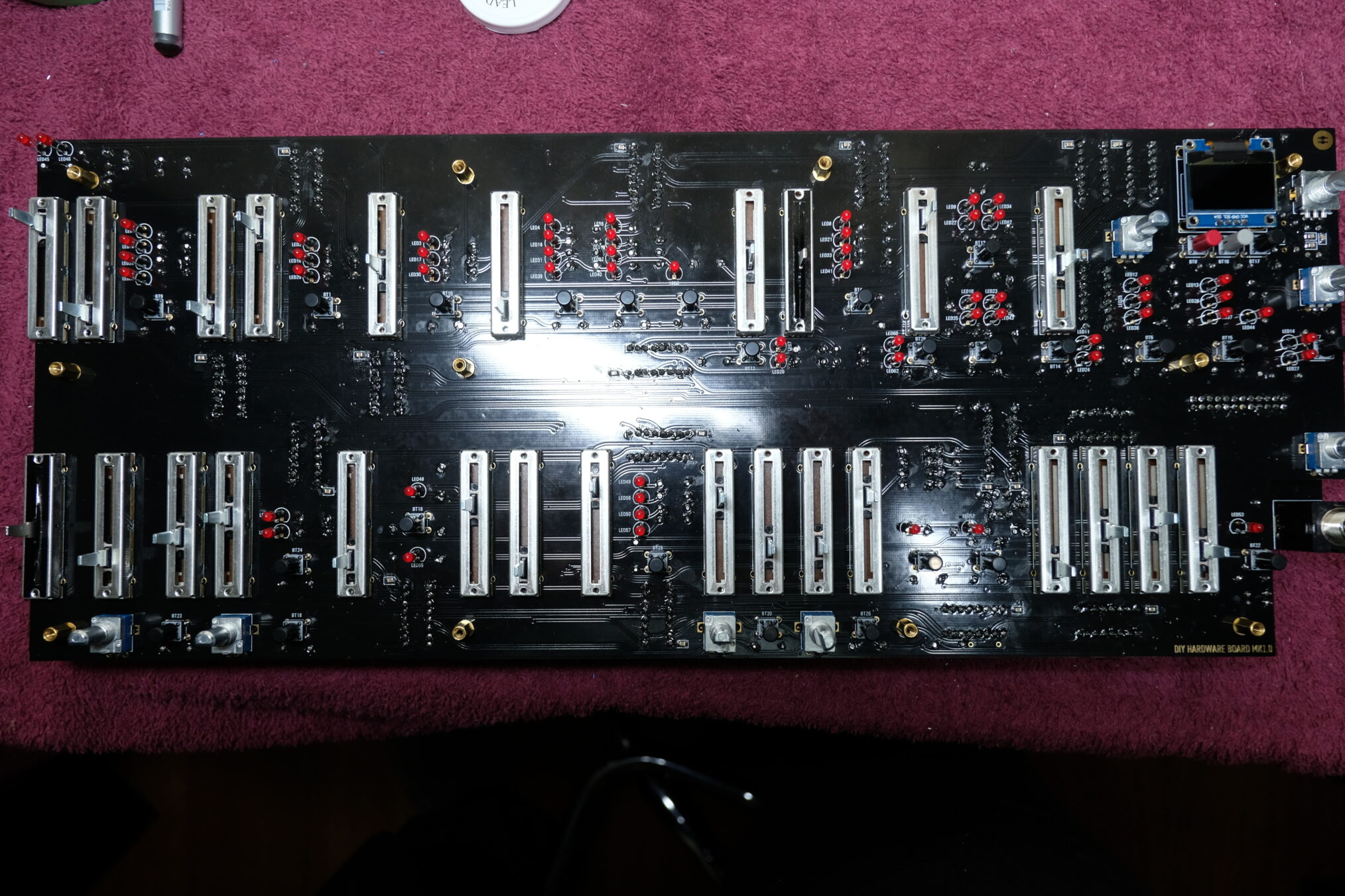
Ensuring the hardware board components sit in the panel correctly.
The voice cards have a few “gotchas” and considerations when building them.

There is a matched pair of transistors.
The sine wave on the VCO utilizes a pair of 2n3904 transistors. Builders do not have to match these for the synth to work, but if you would like a tighter sounding synth, these two transistors need to be matched within +/- 2 VBe. Even if you don’t match them, they should still be thermally coupled with compound and a zip-tie.
The tempco should be thermally coupled to the AS3109 VCF IC.
This is not a hard process to do, but is definitely required to keep the VCF from drifting away from the tuning of the VCOs. This synthesizer can generate a moderate amount of heat.

Higher quality capacitors and resistors could also be used in the VCF portion.
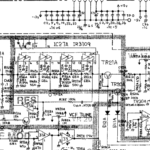
The original circuit found in the JP-8 is shown below.

Roland JP-8 filter section

The ISE-NIN filter design is identical to the JP-8 and JP-6, and was actually implemented as described in the AS3109 specification sheet (above). Here is where sound can be tighten up. The original Roland JP-8 used 10% ceramic disk capacitors (240pF) and 5% carbon resistors ( 68K, 560Ohm) in their construction. This gave the JP-8 and very distinct sound where there was subtle differences between each voice card. But, the entire synthesizer was loose. The VCOs and VCAs were built from discrete components: Resistors, capacitors, diodes, transistors each had large tolerances by today’s standards. In fact I have never heard any two individual Jupiter 8s sound exactly the same.
The ISE-NIN however is highly integrated with 1% metal resistors, 5% X7R and COG capacitors. The point being that there is not the subtle audio differences between voice cards. Everything is tighter giving a more precise sound without sounding cold or digitally perfect. The original design of this type of filter however, required an exacting voltage at each stage of the filter. in many other implementations, the 240pF capacitors are measured between them to ensure they are within 2% of each other. Similar, is the 68K and 240Ohm resistors as they should also be within 1% of each other. For this reasoning, I selected the resistors and chose to use Silver mica capacitors at 1% tolerance. You could also use 1-2% polystyrene capacitors here as well, but they are getting to be harder to find. Alternatively, you could probably build this synth with 5% carbon resistors and 10% ceramic disk capacitors. I just don’t know how it would sound, and would most likely cost the same as 1% metal resistors cost about the same as 5% carbon does. Since the overall design was highly integrated, I choose to make it as tight as possible. The ISE-NIN BOM calls for using 5% COG ceramic capacitors. They will work fine, but I find silver mica or polystyrene capacitors give a slightly different sound.

Improved timing capacitor for the VCO.
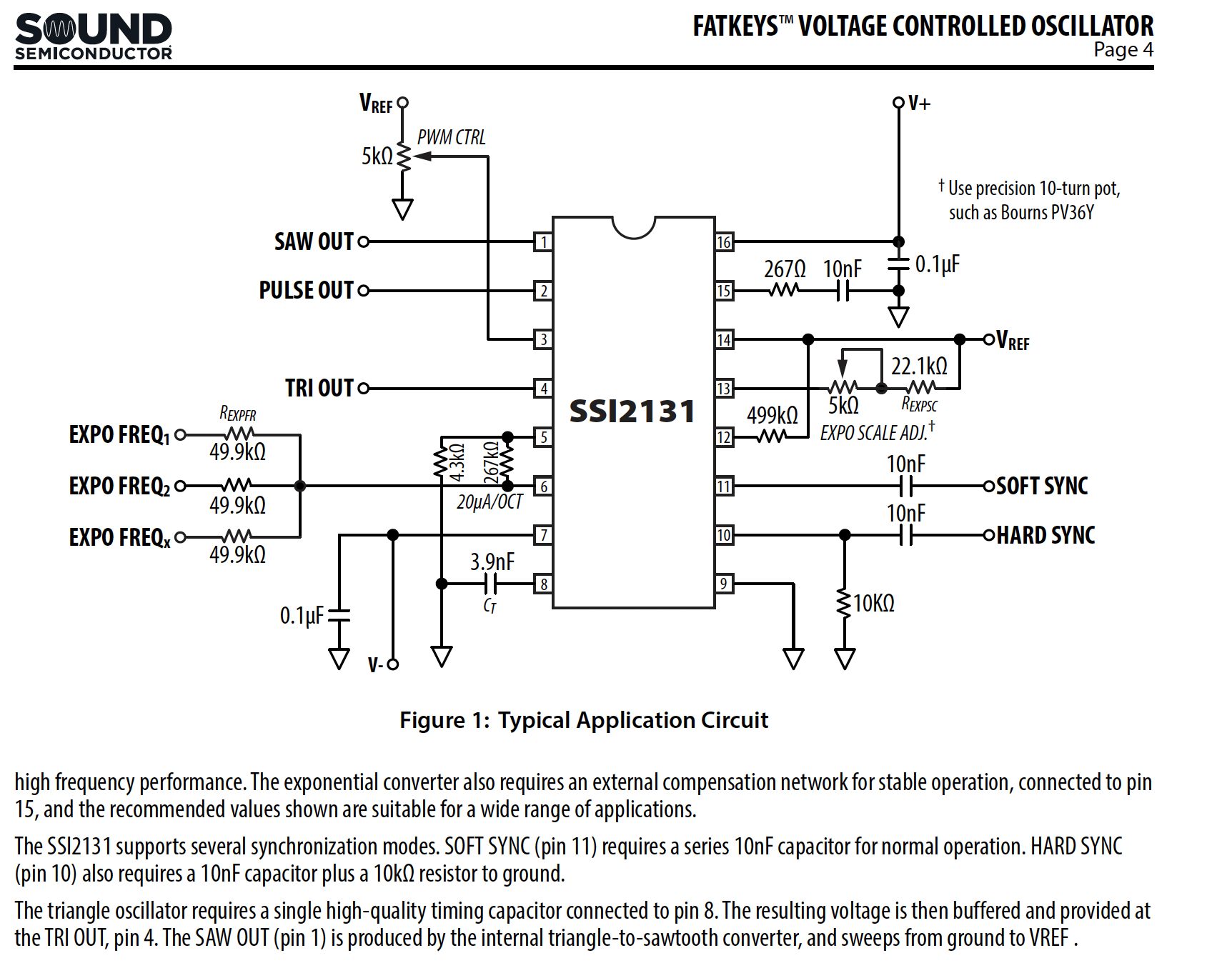
Like the AS3109 filter, the ISE-NIN basically pulls the VCO design from the SSI specification sheet, with a couple resistor changes. There is a discussion online about the timing capacitor (3.9 nF) on pin 8. The spec states to use a “high quality” capacitor. The BOM called for a 5% C0G ceramic type, the online discussion was about using a 1% poly. I actually used a 2% automotive grade C0G capacitor, that was stable at higher temperatures. To be honest, I don’t know if there would be any difference here, and I have not notice any timing drift.
Build issues.
I had one issue where one of the voice cards had a wonky shape to the filter output and it would not calibrate. It turned out to be a faulty AS3109, which was a pain as these are SMT devices. I removed the surrounding transistors to ensure clear access and then using a hot air rework station, I was able to remove the faulty device. I the hand soldered a new device back in place, and also installed new transistors (I have these in bulk). Once installed though, everything work fine.


Uh Oh… More Rework!
A version 1 of any type of project are not for the faint of heart. I have yet to build one that did not need a rework to the circuits, due to errors made in the design or manufacturing process. The ISE-NIN is no exception but luckily, not that bad either.
Rework Item #1-A Oscillator synch.
There is an error in the oscillator synch circuit and required a fix to each voice PCB. The issue is the original connection for the synch circuit went to the soft-synch input and not the hard-synch input. It also did not match the use case on the SSI2131 spec sheet. (See VCO design above).
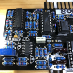
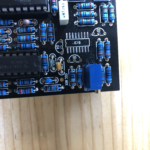
Part A of this rework is by pulling up a single leg (Pin 12) on IC3 (SSI2131) and soldering it to the neighbouring leg (Pin 10). See image below. I managed to do this before I installed the ICs on the voice cards. Note: I mark all rework areas with brightly coloured enamel and record those into a build log for future reference.

Part B of this rework is a little more challenging. In addition to the modification of IC3, you also need to modify the PCB around IC7. This is accomplished by disconnect IC7 pin 11 from C23, Adding a 10K (per spec sheet) resistor between pin 10 of IC7 and GND and then connecting IC7 pin 10 to C23.
This is a bit harder as it requires some careful cutting of two traces on the component side of the PCB (noted in green on the left panel below). I use a micro engraving tool ( inexpensive on amazon), to perform this type of work. You do not want to rush this or use a tool the will damage other traces. With two cuts and careful bending of resistor lead is all this takes. The image below shows that a single 10K resistor is connected to the ground of a decoupling capacitor and the other lead connects to C23 and pin 10 of IC7.
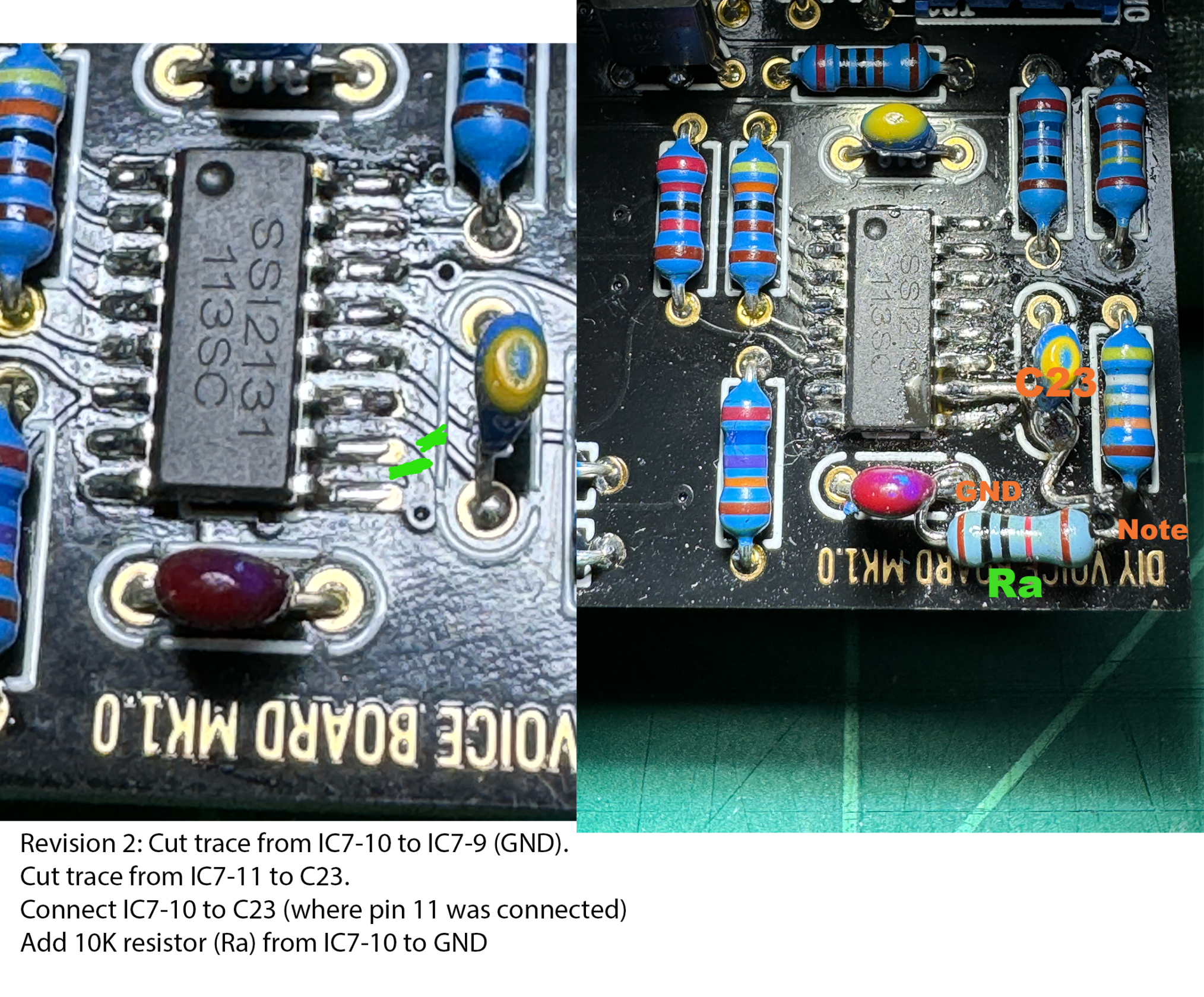
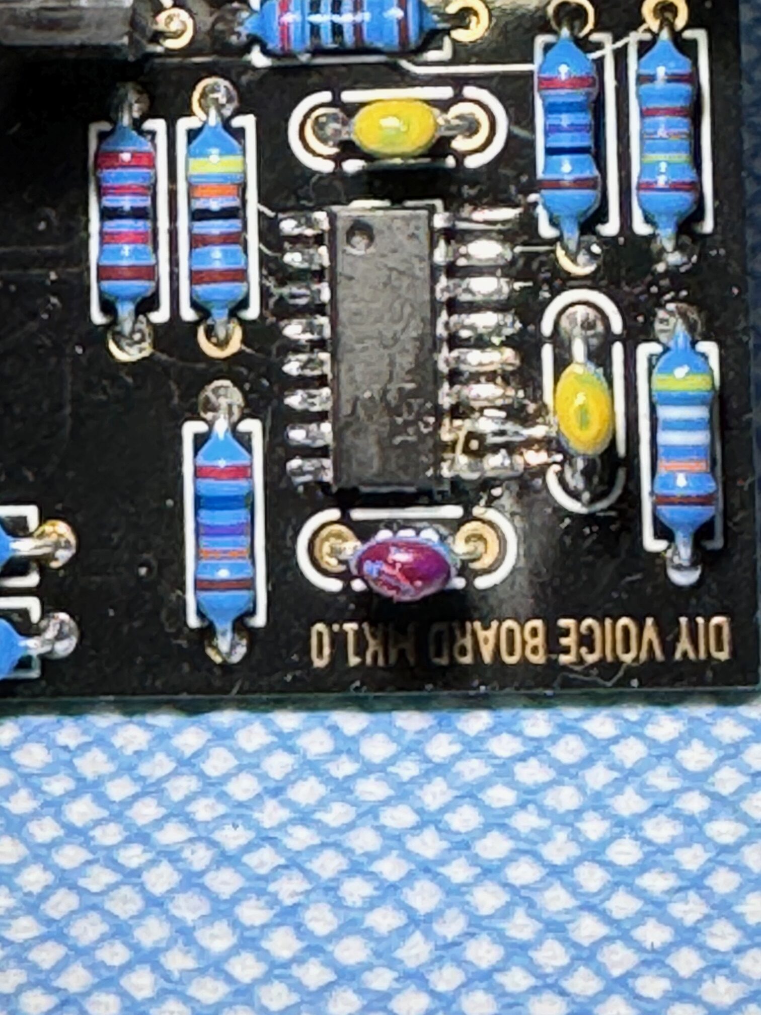
Alternatively, you can use SMD resistor. Since pin 9 of IC7 is also grounded, so you can use a 10K SMD resistor across Pins 9 and 10 and then connect a wire from C23 to pin 10 after cutting the two traces.
Rework Item #2, Resistor R8 on Power Board overheating.
An incorrect value of R8 on the power board was causing overheating of some components. Simply put, there was too much current allowed to pass. This change requires swapping out the 220 Ohm 1/4 watt for something between 1K2 and 2K2 1/4 watt.
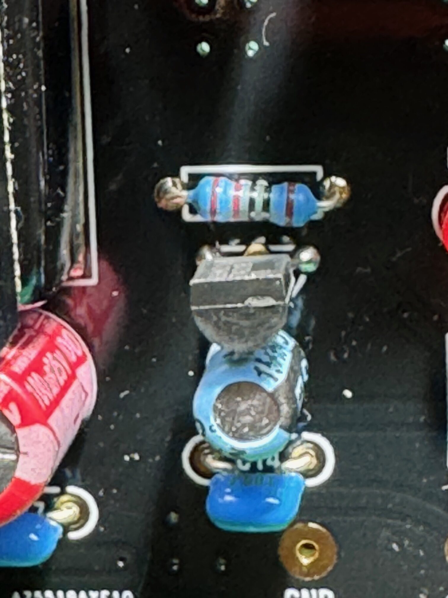 Note the discolouration of R8 from overheating. Change this to a 2K.
Rework Item #3, Volume control not acting in a logarithmic manner.
The main volume of the synthesizer was not acting the way a logarithmic potentiometer should. The issue turned out to be incorrect values of 4 resistors. Change the 4 resistors highlighted below to 1/4 watt, 100K, 1%
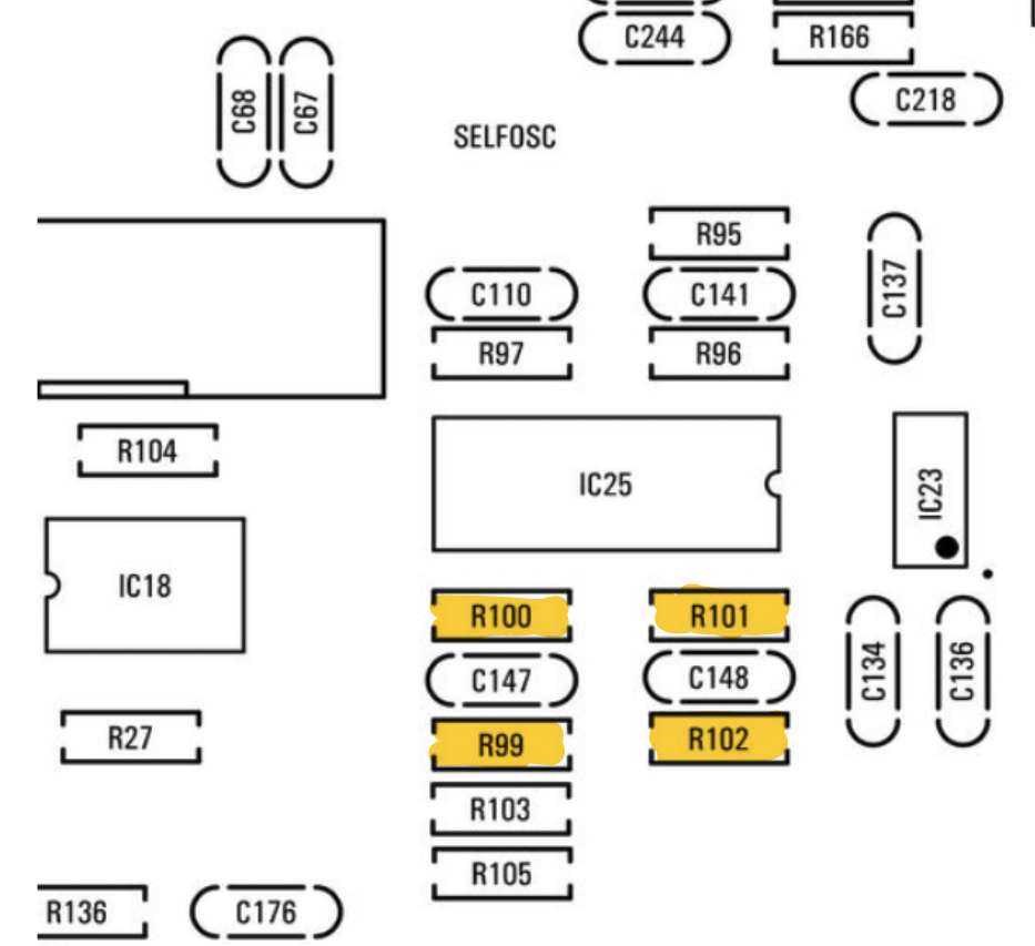 Resistor value changes on the motherboard
Other things to note:
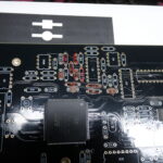
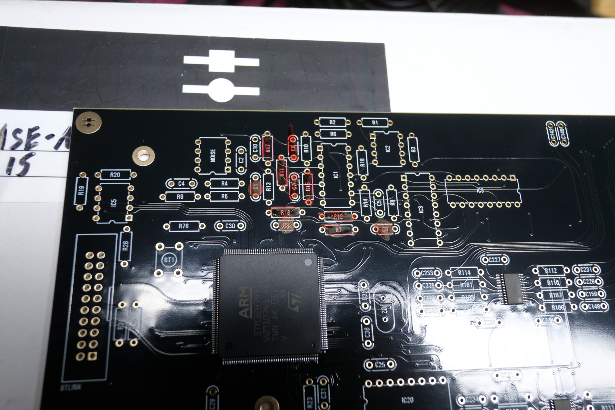
The motherboard also has another rework, or shall I say “ignore work”. The resistors and capacitors marked in red are not to be installed as they were not needed in the design, but made it through to manufacturing. I mark components with a red marker to remind myself that they are not to be installed.
How does it sound?
I hate trying to describe the sound of an analog poly. Nothing beats them, not even mono synths. Yea, yea… don’t give me that “phat sound” nonsense. Polyphonic synths can also be played in mono, only they allow any number of voices to be added in unison, even detuned between them for an incredible phat sounds. Let’s also face facts, most people are not listening to synths in an analog audio path anyway. Nope, they judge the sound of an analog by listening to it on heavily compressed, digital mediums like YouTube. My own studio has either a digital path or a fully analog path where it is Synthesizer->analog mixer->class B analog amplifier->passive speakers. But since you can’t be here, we are stuck with YouTube.
My personal observation is that this is not a Jupiter 8, but it can perform patches and sounds that are just too hard to distinguish between the two. Compared to a Jupiter 8 VST or a digital modelling synth, the ISE-NIN has that analog width to the sound that VST don’t. It also has sounds that can’t be found on a Jupiter 8. Having said that, I do think that this is an incredible sounding synthesizer on it’s own merits. $2300 for an 8 voice, MPE enabled analog poly that can do split layers over stereo is a bargain. All I had to do was spend some time building, which I love doing.
ISE-NIN
Page last edited on May 6, 2024 to add additional rework information.


