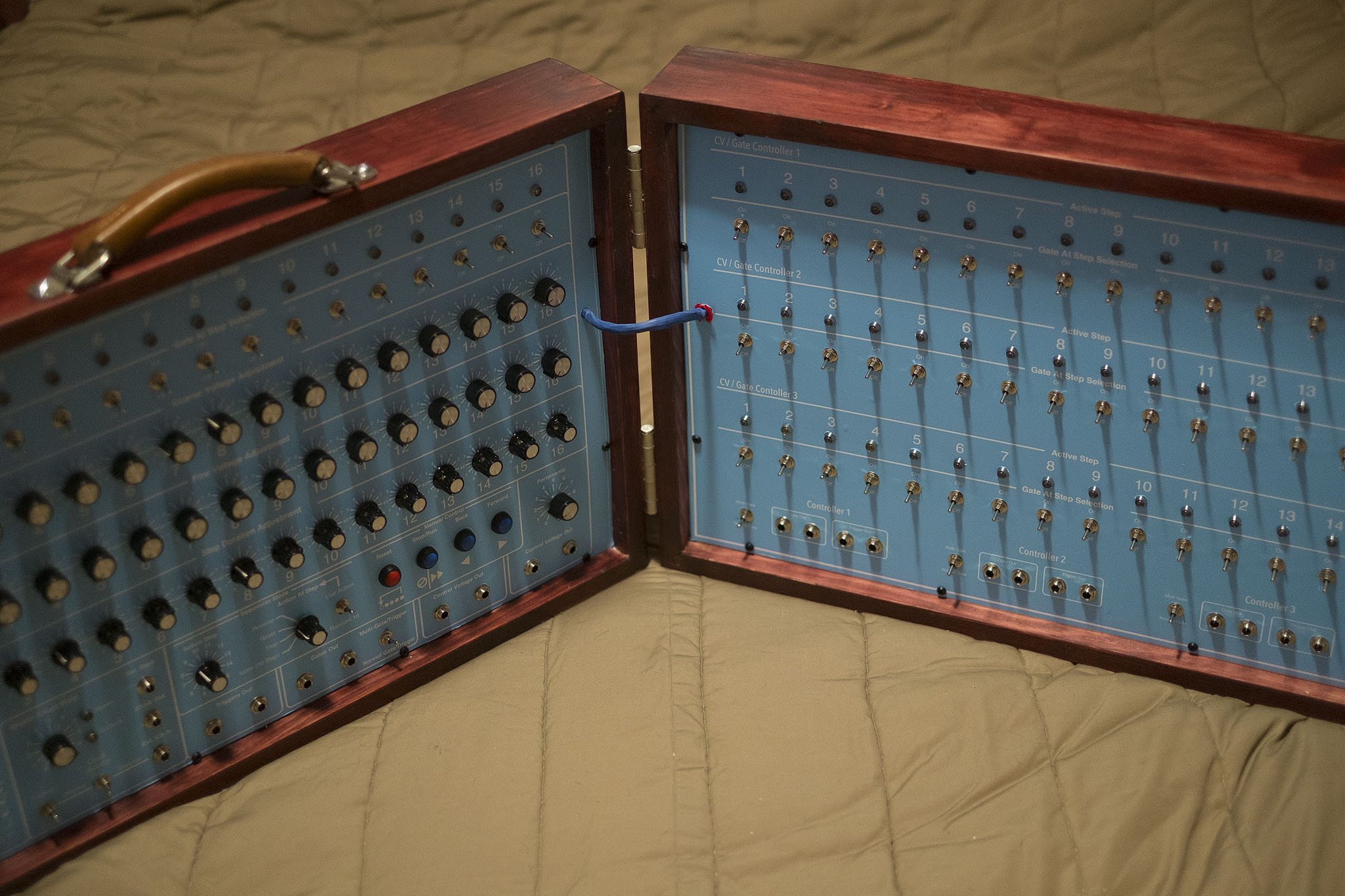
The Quadratic Sequence Machine.
- Based on Ray Wilson’s 16 step vari-clock sequencer
- 3 x 16 additional gate/trigger sections.
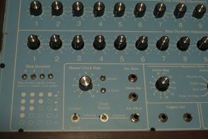
- Minimum sequence can be set from 1 to 5 steps and stop
- Maximum sequence can be set from 1 to 16 and reversed
- Secondary clock provides a 1 to 16 count or beat, for each step in the sequence
I love sequencers. If you are a fan of Tangerine Dream or the Berlin School of Music, you know that sequencers are heavily used in creating layers of complex rhythms. I have always wanted to build one that could be used to trigger multiple synths, drum machines and other sequencers independently across a shared time signature. The quadratic sequence machine can provide much of that. So how does it work?
Basic time sequence:
Sequencers are set to an overall time signature that sets the tempo of the music structure. This tempo is set to occur over 1 to 16 steps that can either repeat (step from 1 through 16 repeatedly), go through the steps once and then stop, step up and then reverse back down repeatedly, or just randomly hit a step. The tempo is the time between each step and can be slow or very fast. It is the time count.
At each step, a switch determines if the gate is on or off. If anything is plugged into the gate, trigger or CV output it will “Fire” a signal down the cable. Remember that CV controls the pitch, Gate controls the length the pitch is held and a Trigger signals the start and the end of a gate. With each step, there are also pitch controls that cause whatever is plugged into the CV output to change pitch.
So, a basic 16 step musical sequence can have a synth plugged into the CV, and a kick drum machine plugged into the Trigger. For each step that is switched on, the synth will play the note set by the pitch controls and it will also have a kick drum occur. That sounds fairly simple, but let’s consider something really complex. If I plug other sequencers into the triggers, that are connected to additional synths and set to different time signatures, you can imagine very complex rhythms being created. The main sequencer can step at 1 step per second, while the other sequencers can be set to 3 steps per second. So while one synth is playing a slow rising and falling musical beat, the other sequencers can be running faster (or slower) musical rhythms at the same time.
Anyone who plays with any of the musical production software apps out there are doing this now. They just lay down a new track for each sound or beat they want. One overall time signature is made out of dozens of sounds running on shorter signatures. Back in the day though, if you wanted to play a live event, you needed sequencers to provide that control. This part of the sequencer has 4 CV outputs, 2 trigger signal outputs and 2 gate signal outputs. Sequencers can also be triggered to share their clock or run independently whenever they are triggered. Imagine if I had my main sequencer running at 1 step per minute, at each step two other sequencers could fire and start independent musical rhythms that each lasted a minute or run until the next step occurs in the main sequencer.
Vari-Clock sequence:
To really get complicated time signatures without having to use many more sequencers, another clock is added. This clock, will control the number of ‘Beats’ each step will provide. So instead of each step firing just one CV, Gate or Trigger signal. I am going to enable it to have anywhere from 1 to 16 beats at each step. Furthermore, each step can be set independently from the others. So the first step can have 2 beats, the second 1 beat, the third 4 beats, etc. Rays Wilson invented this circuit and it’s simple design makes it all the more elegant. But I can also set the gate/triggers to fire a signal for each beat or hold the gate for the full duration of the total number of beats for that step. Back to my first example though, with the synth and the kick…. what if I wanted to have the kick or drum machine fire at different steps than the musical synth?
Additional gates:
By adding the additional gate/trigger controllers I can now build a sequence where a synth can provide rhythm on the main CV output and a kick can be fired at every 4th step 1-4-8-12-16 (using the very-clock I can actually set step 8 to be 2 kicks so it sounds like kick—kick—kick-kick—kick—kick-kick—kick—kick-kick and on and on. Meanwhile, I can take a high hat and have it trigger at every 6th step and a cowbell at every 2nd step. Get where this is going? I can also add sequencers…….
The build:
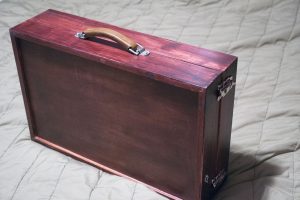
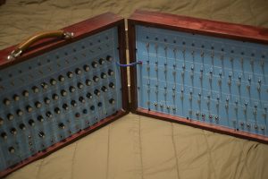
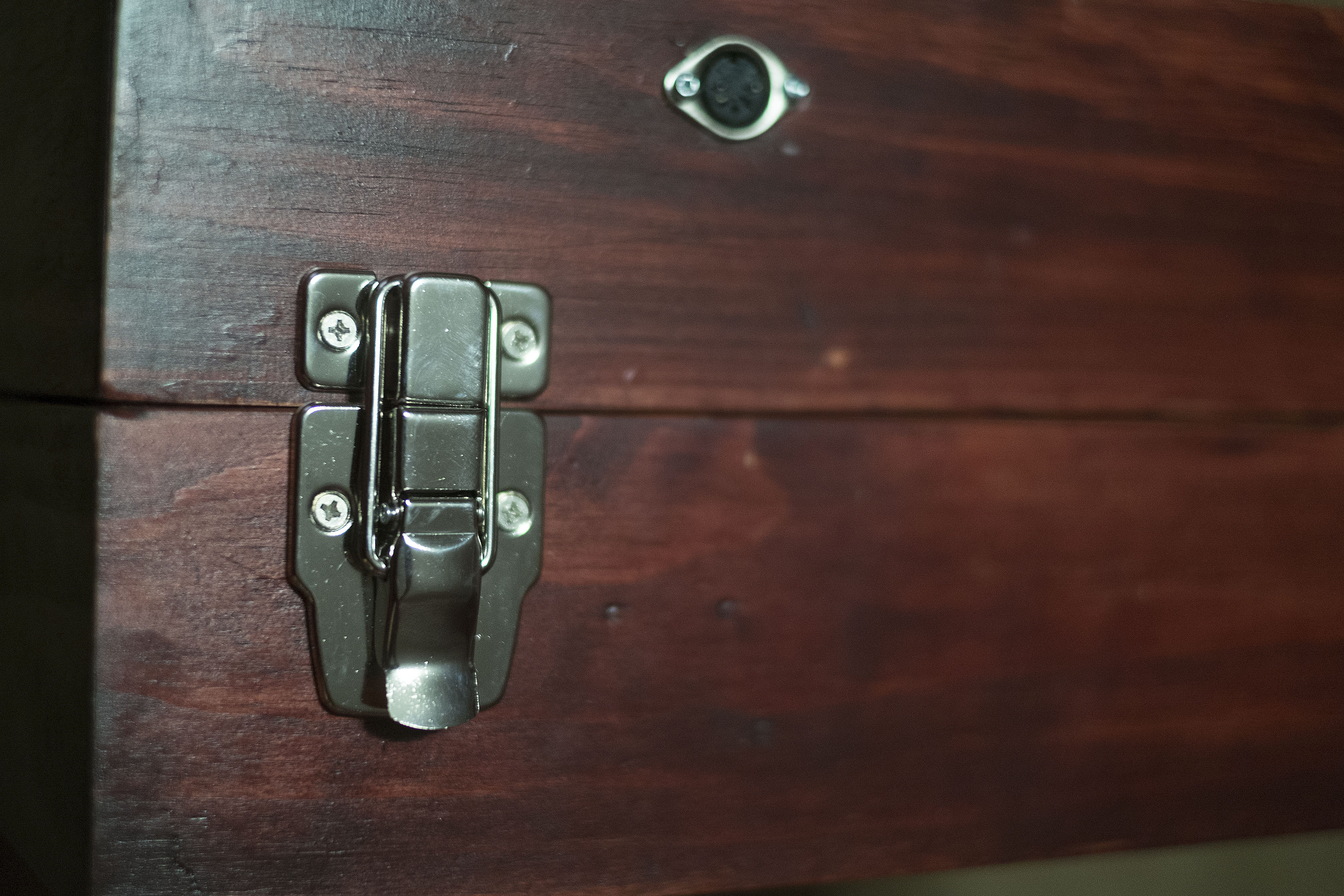
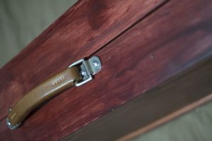
I had a bunch of ideas about this because I changed the direction several times. I was going to build the whole thing into a giant plastic tube with knobs and switches all around the perimeter and lit up on the inside. In a sense though, this is an analog computer and can be difficult to wrap your head around the time signatures and configuration of the final outputs. Having remembered that I have to use this in a live performance, it has to be fairly straight forward to use, be somewhat portable and look like something it is not. I thought of using an old sears wooden suitcase from the 1920s. I went to buy one, and was shocked to learn they are several hundred dollars. So I built one out of scrap wood. Basically two identical frames with backing (the leftover sub-floor panels I am getting many synth build miles from). Some hinges and latches from Lee Valley, some stain and an old leather handle salvaged from somewhere along the way. It can fold up and be moved to a gig, sit on a table or actually hung on the wall like a double picture frame.
I standardized on the power with all the big tuneable synths using a 5 pin DIN connector so there is +12V, -12V, GND, +15V, -15V and I don’t need to worry about plugging 15 volt in 12 volt and visa versa. It may fit, but a 12V synth are not connected to the 15V rails. My 5V and 9V synths use a different connector. Instead of hand wiring, I purchased printed circuit boards (PCBs) and sourced the components myself. The PCBs make the build easier and less error prone than hand wiring, but this build does require some advanced electronic knowledge to get it working correctly. The vari-clock oscillator utilizes a CD40106 Schmitt trigger inverter (U1) with a capacitor (C17) and resistor (R26) to provide the timing pulses. In fact, it needs to be running at 54KHz +/- 1Khz. With the tolerances in manufacturing, that is going to be really hard to achieve without pre choosing the components on a separate breadboard prior to installation. My initial timing was way off and on the scope, it was running about 84KHz so I added a 20K trimpot at the end of R26 and was able to tune the frequency down to exactly 54.010 KHz and now the vary-clock tracks and counts perfectly. See the schematic here. If you want to build this circuit, just replace R26 with a 50K trimpot and Bob’s your uncle.
For a short demo with the Delphichord and the new Slingerland TR909 clone, try HERE.
A short demo of the sequencer HERE.
For more info, visit Ray Wilson at MFOS
