Building the TTSH
-
Building the main components (see below)
-
Modifications
Building the VCOs

The VCO is the heart of any analog synthesizer. What separates a simple oscillator from a VCO is the ability for the VCO to proportionally change it output frequency based on the voltage that is fed. I have talked about VCOs and VCFs in other past DIY projects, and for the most part, these are really no different. For the TTSH, just like the ARP2 2600, there are three VCOs which are slightly different. The differences lie between how they are modulated and what waveforms they provide. But the core of each VCO, is identical. I guess this is why the Arp designers made the core a module that is “plugged in” (the arp was actually soldered) to a PCB mainboard or carrier board. The module is critical to ensuring that the synthesizer maintains tracking (the ability to maintain a musical scale) as voltage is increased, even across 5, 6 or maybe 7 octaves. To do this, multiple pairs of identical transistors are required.
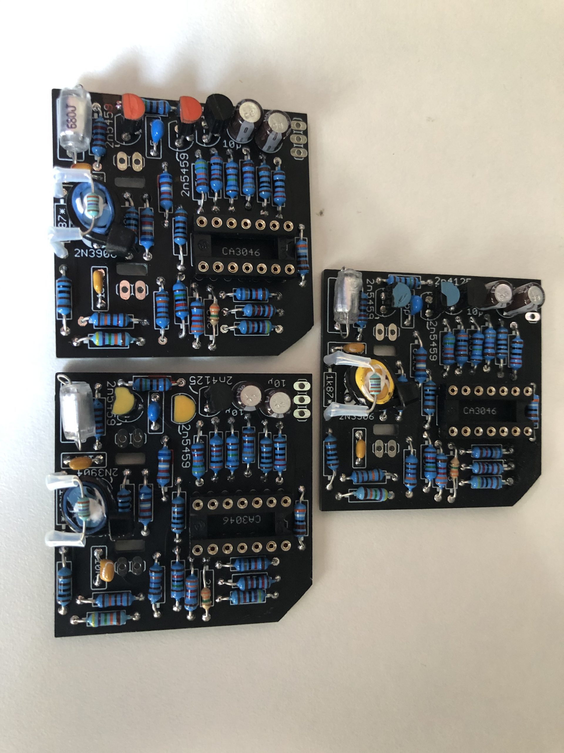
The image above shows the 3 TTSH 4027 oscillator cores and a 4027 core from an LS Arp 2600. The latter module is part of a 1:1 Arp 2600 clone where circuits can act as a direct replacement for circuits in an Arp 2600. In both cases the circuit (electrically) is identical as the one found in the Arp, but layout and components are different. Theoretically, you could build both with the exact same component types and I doubt there would be much of a difference on this circuit (filters would be different). Example, the TTSH utilizes a complimenting pair of 2N3906/2n3904, a pair of 2N5459 JFets and a 2N4125 NPN, while the Arp uses a complimenting pair of TZ-581/TZ-81 (Listed as part number A-40127-008 with 2N5367/2n5249 listed as an alternate), matched 2N5459 JFets and a selected 2N5910 (or NTE106) NPN. Although the TTSH notes do not state that the JFets should be matched, I did match mine.
One problem I also had with the Synthcube kit, was that the 2N5459 JFets they supplied did not meet the Vgs specifications on the data sheet. Fortunately, I had some in my stock that I could replace. The other issue with the Synthcube kit is that none of the transistors are matched. And you only get the required number for the entire build. It is really important to verify transistors against the spec sheets prior to installing them. There is a huge inventory floating around the world that is basically rare or hard to obtain JFets, etc that did not meet spec. They may in fact work, but the JFets Vgs or Idds specs may operate outside what the circuit designers intended.
Many companies I previously worked for, all had internal material handling sheets or process build instruction or envelope drawings (although the later can be really complex assemblies). For instance, if I wanted to use an off the shelf LM301 op amp, I would just put LM301 on the schematic. However, if I wanted to instruct the builder to take 50 LM301s, and select the one with the lowest input offset voltage, I would write a process instruction and denote that, on the schematic instead. I may also want the builder to cut a leg of a 2N3904 transistor for generating some weird noise. I could write PS-1983-001 (arbitrary number) instead of 2N3904 and a note stating “Cut the emitter leg off the transistor prior to installation”. Using a process spec as a part number also ensured you got the correct (and processed) replacement part for in field repairs and service.
Sometime you would put the preparation and handling of many components, on one or two process sheets or even use them across many different product lines that required the same part/process. In the case of Arp, they have several listed on their schematics instead of manufacturers part numbers or generic component type. So I relied on the evidence from those early conversations I had with Gary Benson, the Arp service manual schematic notations (in this case A2803-003-1) and industry practice back in the day. It was common practice to colour code processed components with coloured enamel (I use hard, bright nail polish). I also remember looking at those early Arp modules I had and the Jfets I saw had the same colour code (enamel) on both JFets. It was also in my notes.
transistor matching refresh.
Although I never saw the actual Arp process sheet (A-40127-008 noted on the schematic where the NPN/PNP are located), the TTSH build specs state to match the Hfe of the NPN/PNP pair within +/- 10% of each other. And within an Hfe range of 180 to 220. So I am going to assume that is what the selection criteria from Arp was too. In this build they are all matched within 0.1% Hfe. My only other note I had from the 80s was that the 2N5910 transistor should also have an Hfe of >100. Does the TTSH really need this for the 2n4125? I ensured all the ones I used met that spec, but I would love to hear if other people are measuring and recording these metrics.
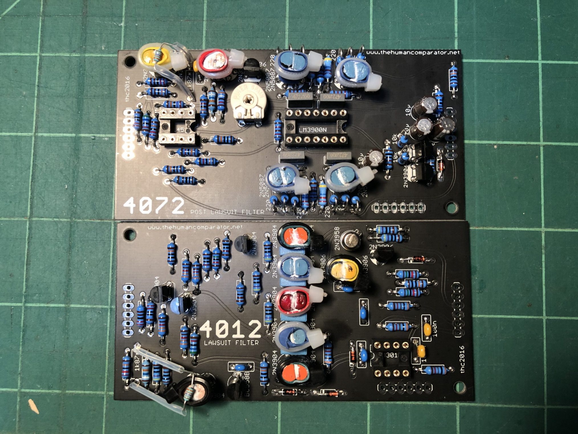
I also keep notes by recording the colour coding I use. Here you see individual JFets (Orange top, Blue right and Yellow bottom), colour coded by Vgs value, and complimentary NPN/PNP pairs (Blue top, yellow right and blue bottom). These too are recorded in my notes. So in this case, the Hfe colour code meaning is: Blue Hfe = 178, Yelow Hfe = 187; There are two pairs of transistors with the same Hfe. This process allows me to backtrack once everything is built and really assists in debugging should say the core not maintain tracking. It also provides additional information for people to know what works and what does not.
Interesting note for synthesizer history: That small resistor on top of each NPN/PNP pair, is a temperature compensation resistor (TEMPCO). As temperature changes, it is supposed to provide compensation for the oscillator, in order to maintain stability. Interestingly enough, Alan R Pearlman invented this process, and was awarded a patent on it. Moog licensed this method from Alan. This enabled analog synthesizers to stay in tune, as temperature changed. In the 4012 filter, Arp had them hanging just off the circuit board and not in contact with anything like depicted above. So I am not sure if the way I did it was that critical. What is critical however, is that all matched transistors and complimentary pairs, maintain the same temperature as a pair. This means they are held tightly together with thermal compound between them. In the end, calibration was a breeze and all three oscillators track beautifully and well over 6 octaves.
Building the 4012 VCF
The Arp 2600 came with a different filter depending on when that particular Arp model was made. All of the early versions along with many of the 3rd revisions all came with the 4012 ladder filter that was pretty much right out of the Moog collection. Somewhere along the line, they got asked through some sort of “legal agreement” with Moog (I have never seen any evidence of an actual lawsuit), to stop using this design. So, in later models, Arp came up with their own 4072 version which pretty much comes out of the Odyssey collection. Needless to say, it is a different filter and has a much different sound. I think both are awesome, but will admit the ladder 4012 sounds phatter than the 4072 in the lower range, but in upper ranges I think the 4072 sounds wider. Having said that, you get both filters with the TTSH… but you have to decide which one you will install. It take about 20 min to change out the filter board. Note that both the Korg remake and Behringer clone come with both filters installed and a selector switch.
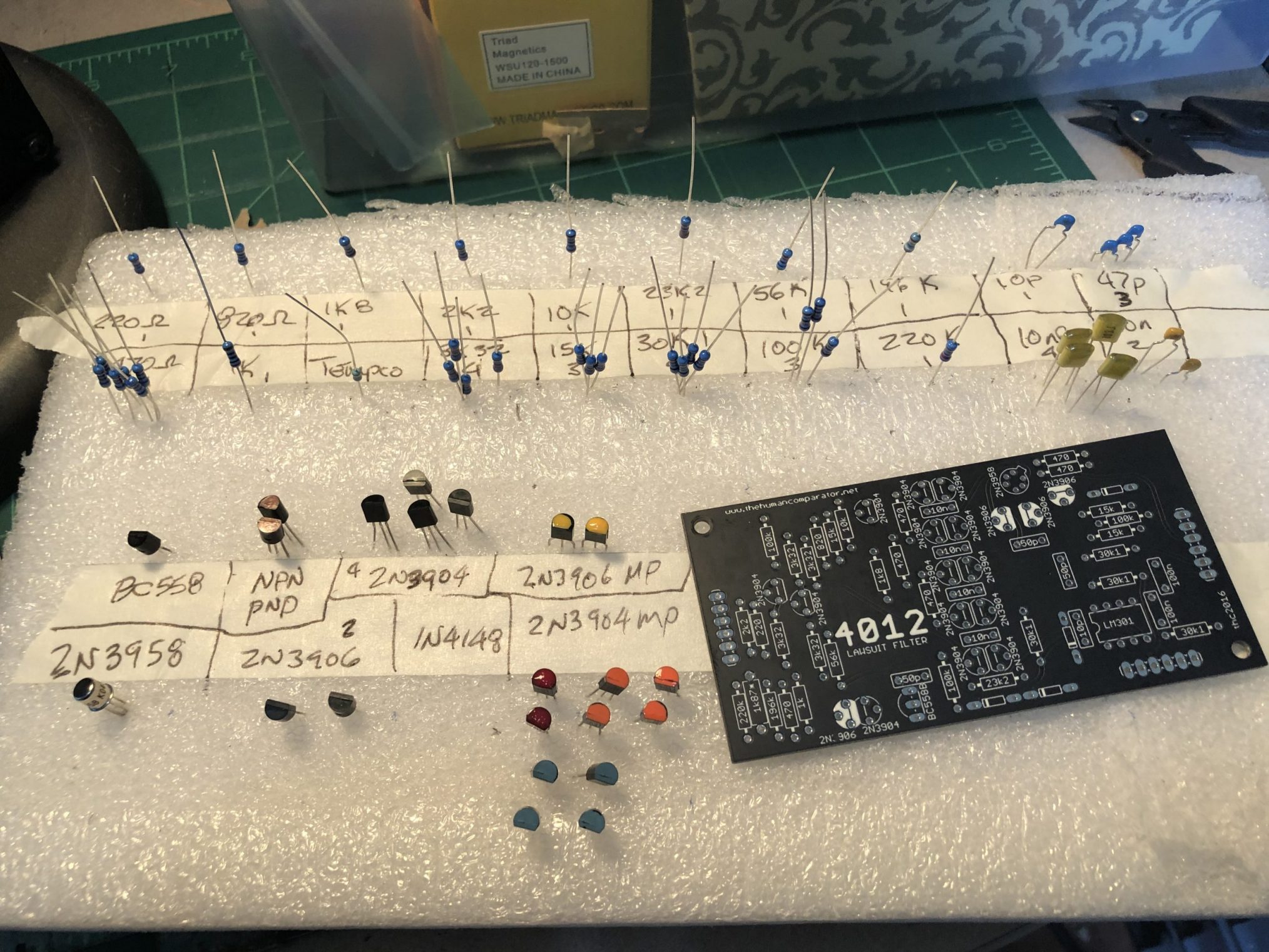
Like the VCOs, you had better love matching transistors, because the 4012 uses 6 matched pair, and one complimentary pair on the module alone.
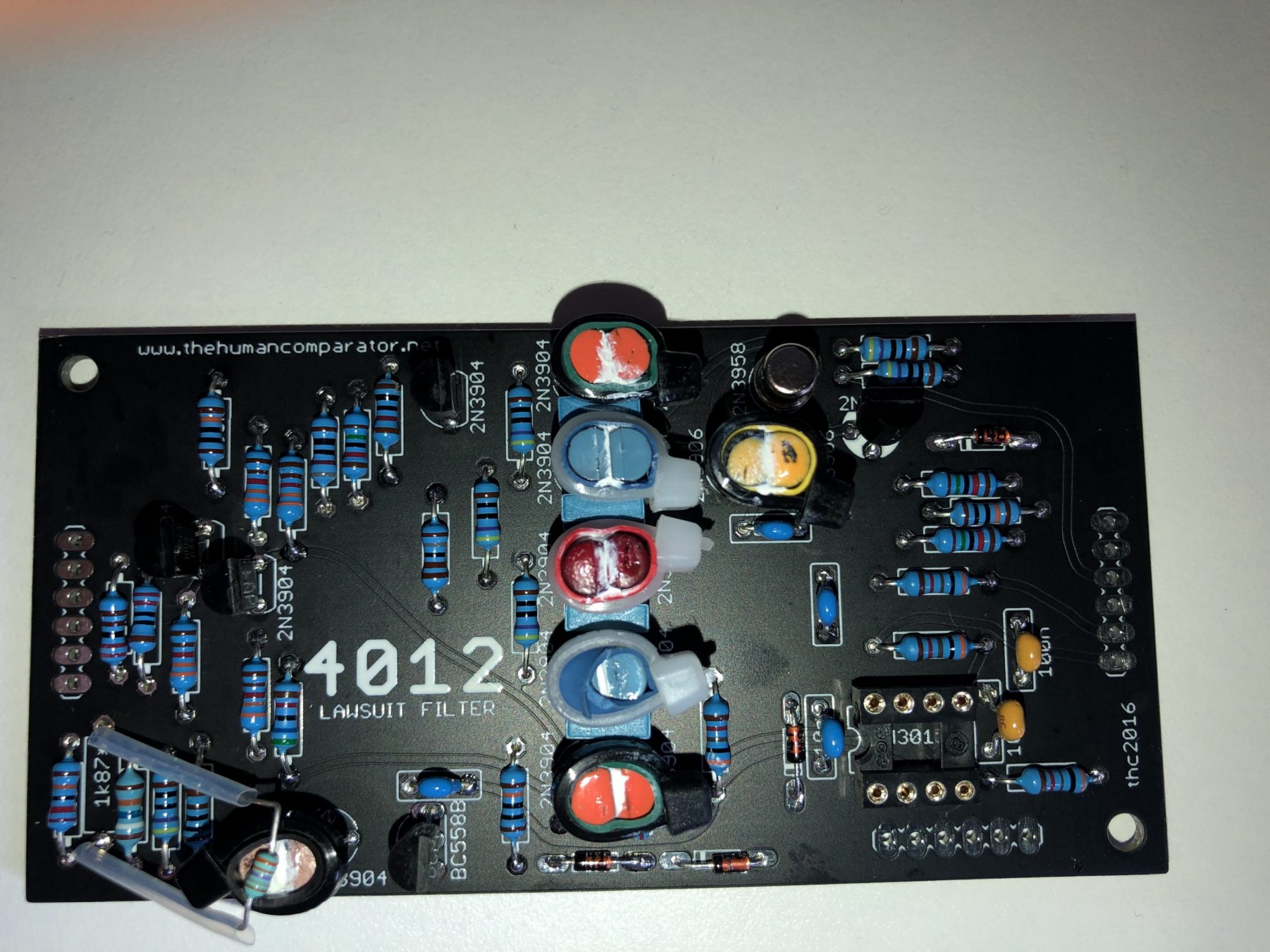
4012 Ladder Filter VCF
Again, there is a TEMPCO used in the design to compensate for temperature drift. On this circuit, the design calls for a LM301 but I intend on using an MC1539G or LM218 in this location. The original Blue Marvin/Grey Meanie used MC1439G op amps, which were fast, audio quality op amps. It could even be that the very first units may have even used the 1339 Op Amp from Teledyne Philbrick.
Note: Teledyne Phibrick is a later derivative of two companies. Alan R. Pearlman, was cofounder with George Philbrick, of Philbrick/Nexus Research which was later sold to Teledyne. It was during this transition that Alan Pearlman developed his company Tonus (later ARP Instruments) and designed early Tonus 2500 modules. What I find interesting here is, if you look at how the product modules were made (from the Philbrick link), and how they were numbered, packaged etc in the Philbrick catalog, you can certainly see how those production methods influenced how Arp implemented their own production methodology. From the potted bricks to the pressed pins and the numbering scheme. I have heard many people state online that Arp built them this way to prevent people copying the design. There may be an element of truth to that, but from my own experience in aerospace, potting compounds were used to provide a higher resistance to shock, vibration, and most of all moisture. The carbon resistors back then did not like moisture, and would literally change value if they got damp. Worse, would be chemical reactions between metals should the boards be near a coastal temperate zone. This is why many aerospace products back then had to have a shelf life of 10 to 15 years, in a regular storage facility. Why reinvent the wheel, when the wheel works perfectly.
Although the original op amp in this VCF was the MC1439G (the MC1539G is higher quality), later models (and the TTSH), the schematic mentions SL19986, which specifies a selected LM301, which entails finding one with the lowest possible input offset voltage. The MC1439G has a relatively low input offset voltage and a whopping 34uSec slew rate As a note to any other DIY builders, I fully tested the TTSH with the required LM301s everywhere first to ensure calibration and correctness. Then changed out the op amps to MC1539s, LM218s, AD711s and re-calibrated. Is there a difference? Yes, but that comes later.
Building the 4072 VCF
Did I say that matching transistors is fun? Like the 4012, VCOs and anything that needs to maintain a consistent, proportional output, matched pairs of transistors are critical. The 4072 filter is no different. It should be noted however, that many analog synthesizers designed after the late 70s, used “all-in-one” integrated circuits to provide the functions of a VCO, VCA or VCFs. In fact, this IC method is still used today and allows designers to build synths with 8, 12, 16 or even 32 voices of polyphony a lot easier.
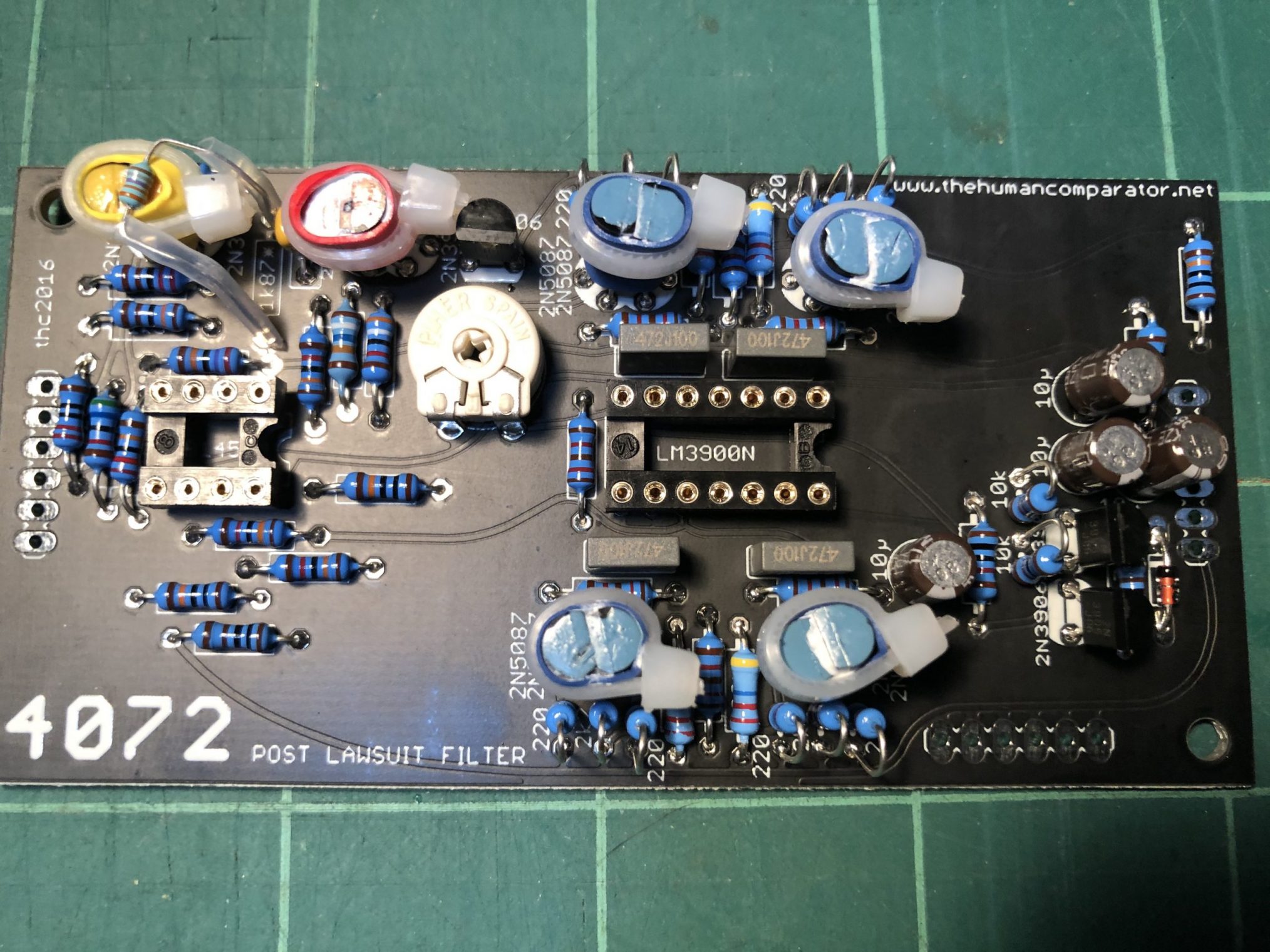
I like this filter, I really do. It has a unique sound not found in many other synthesizers. I wish the TTSH design allowed it to run with both filters installed and have a switch to change between the two. Again, building the VCOs and VCFs, is not hard. But it is very meticulous and most of the time was spent matching transistors, and measuring everything against the component spec sheets.
For many builders in the DIY community, complicated projects like the TTSH, Deckards Dream, etc, never become fully functional or working synthesizers. Most of it is because they face a litany of errors in the build, and don’t test until everything is completed. Yet this is easily solved by eliminating most of the errors beforehand. Having to debug a complicated synthesizer that has multiple errors or issues can be daunting. Imagine trying to debug this synthesizer, if one VCO was not working quite right, and all because one transistor was faulty in the voltage control section, or you had multiple faulty components. It is like the old adage: “Measure twice, cut once”. I guarantee you, taking all the time upfront to check components and implement an inspection process into your workflow, will greatly improve your success rate, and minimize debugging when the project is finished.
The Main Board, Component Side
Remember how much you love matching transistors…. yes, there are more!
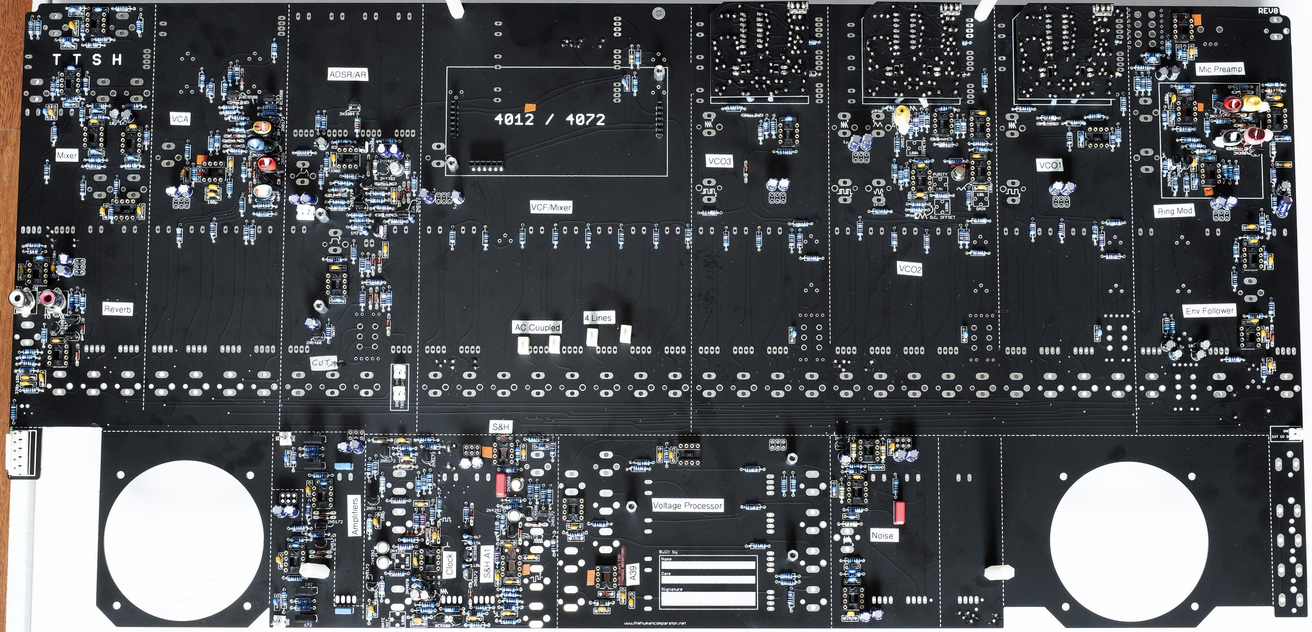
With the Arp 2600, the VCA, VCO2 wave shaper, Ring Modulator we all separate module boards like the VCO core and VCFs. The TTSH however, places these all on a single main board, so these areas will also use matched transistor pairs, and some rare or expensive components as well. In the image above (right click and choose “open in new tab” to see a higher resolution image), you can see these locations by the colour coded enamels.
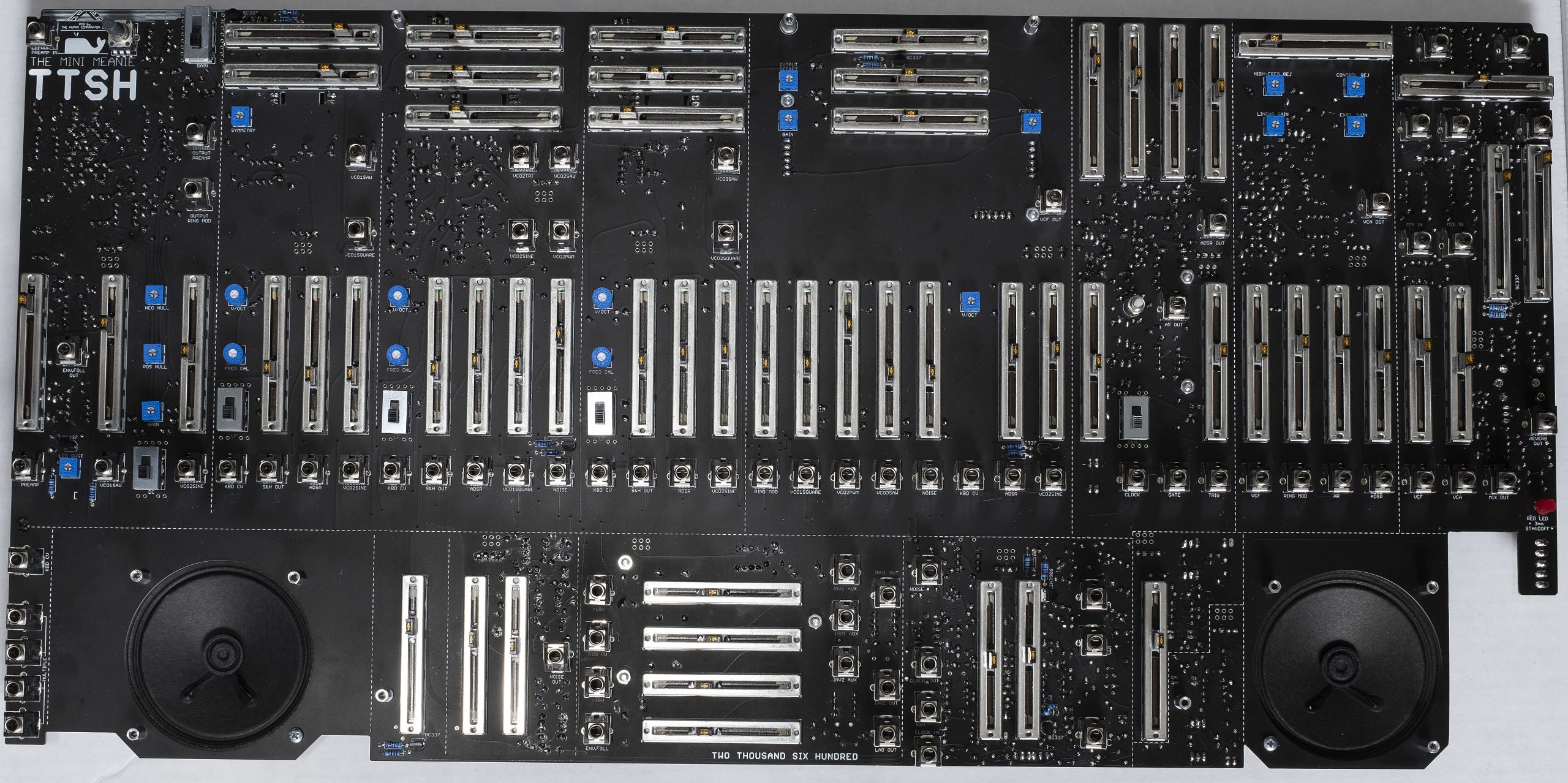
I would have preferred having 5 separate sub boards, rather than one large PCB. One the hardware and components are installed, this board is heavy and hard to work with. I actually think the PCB is too light (material-wise) to be used this way. It certainly saves on interconnection wiring errors, but builders should be careful when handling a fully stuffed main board.
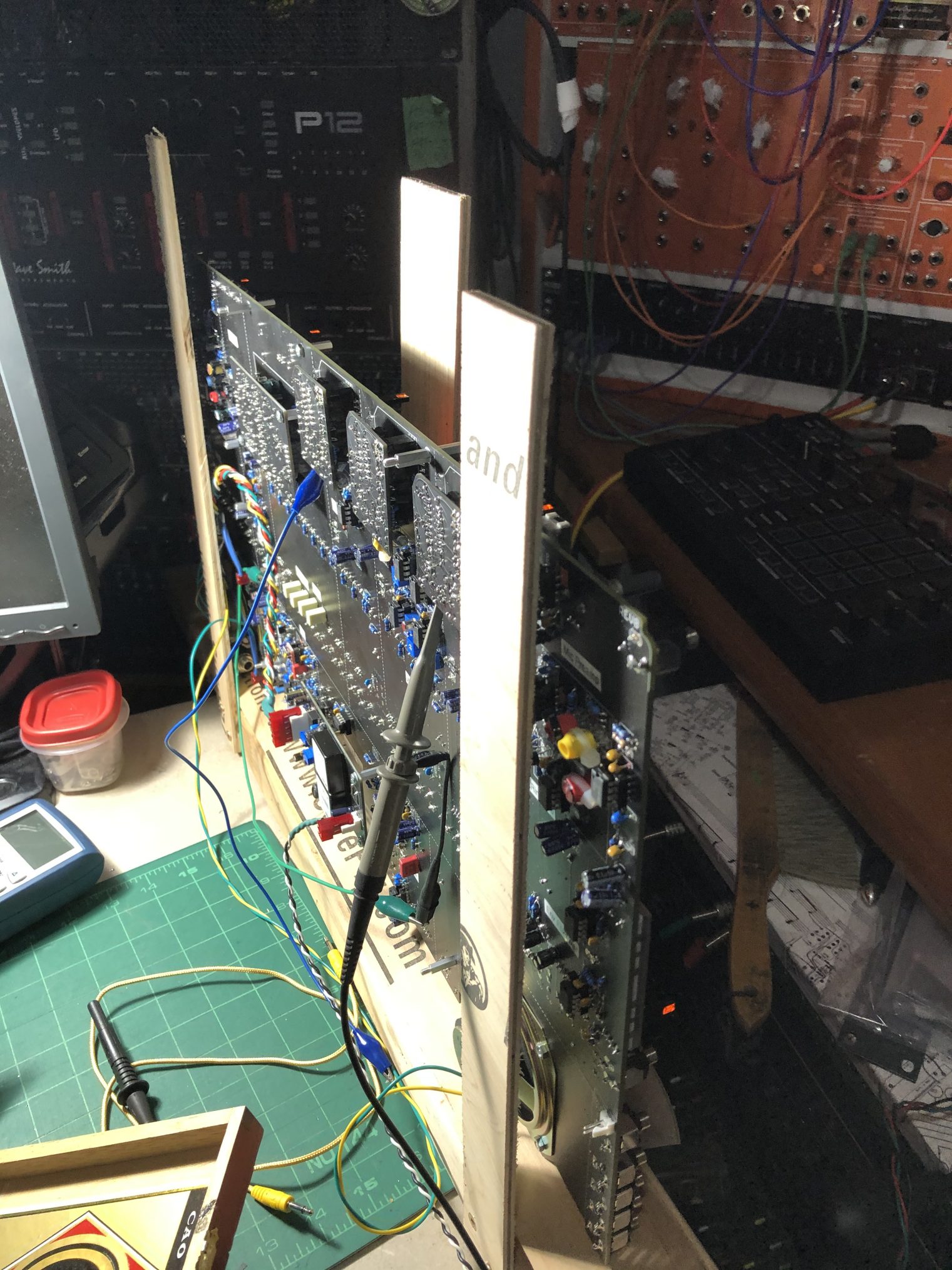
I ended up building a customized jig to hold the entire PCB on its edge. This allowed access to the sliders and switches while calibrating and testing. There are some trimmers on both sides of the board that need to be adjusted, during calibration. The jig really helps minimizing handling of the assembly.
Powering the TTSH
The original Arp 2600 was powered by a 110V AC to +/- 15VDC linear power supply. (Europe would be 220, 50Htz) and you could certainly use your own power supply for this project. The TTSH was designed as a DIY project, where many of the designs tend to ensure safety by reducing any contact with voltages and current that can kill. Therefore, the TTSH uses a 12VDC wall adapter with a pair of DC/DC converters to provide the +/- 15VDC the circuit requires.
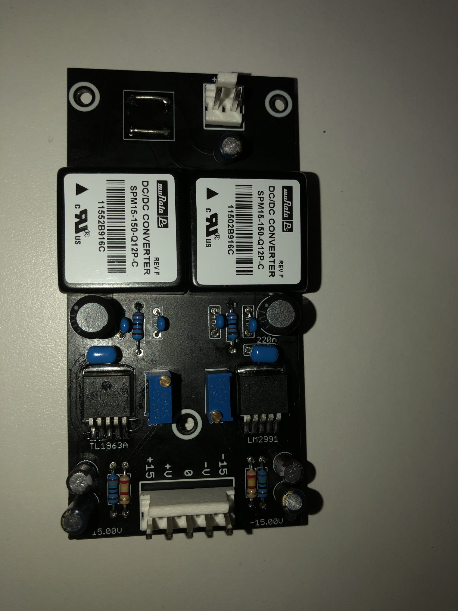
Builders note: I personally think any wall adapter should provide headroom above the required power rails. In this case, you are basically converting current to obtain the higher voltage. The wall adapter is rated for 1.5 Amps, and total current draw is close to 500-650mA (each side), depending on additional mods.
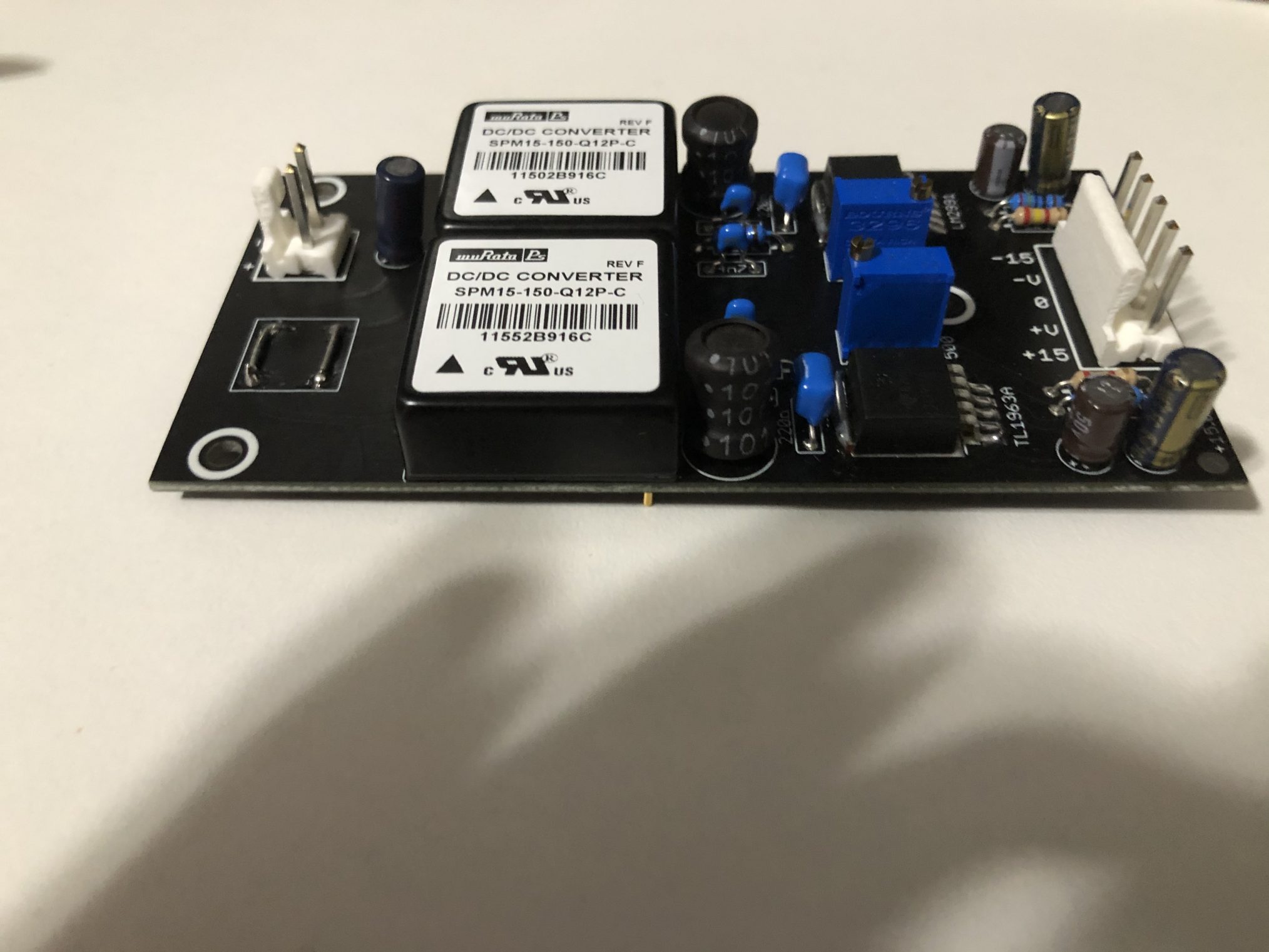
Although this setup does work, you may experience a higher noise floor with the reverb, etc. So, grounding the case to Earth can assist. I may modify this (down the road) to a linear 110VAC- +/-15VDC supply utilizing a centre tap main transformer with higher headroom.